Software defined instruments are very useful tools, specific hardware can be used in many ways depending on the software (firmware). At the Laboratory of Videometry students are developing various SDIs under the supervision of Associate professor Jan Fischer. The instruments proved to be very useful both for home education as well as an entry level education of “practical electronics” at the university. Students use the circuit with STM32F042 microcontroller both to evaluate basic electronic circuits using the SDI (PWM generator, voltmeter, oscilloscope) and later also to run their own programs. In such a case one needs another microcontroller to run for example the SDI oscilloscope to see the signals on various busses, PWM, sensor outputs etc. For this purpose we prepared here at MAGLAB a slightly modified circuit and designed a PCB suitable for mass production. We used a professional PCB manufacturing and assembly service for the SMD components and finished soldering of the through-hole connectors here at the university to save some money… Then we distributed the modules to our students and they use it now during distant teaching of the “Laboratories of industrial electronics” subject.
At the end of the page you can find all the data needed to build the device by yourself or to manufacture it in larger quantities for the education purposes. NO WARRANTY of any kind on the published data. The files are “PostcardWare”, yes, you are supposed to send a real postcard to our department* if you find the data useful. Please contact us in case you would want to use the device commercially.
*Department of Measurement, CVUT – FEL, Technicka 2, 166 27 Praha 6, Czech Republic, EU
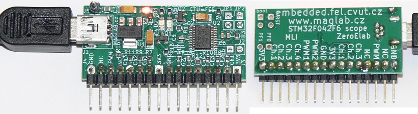
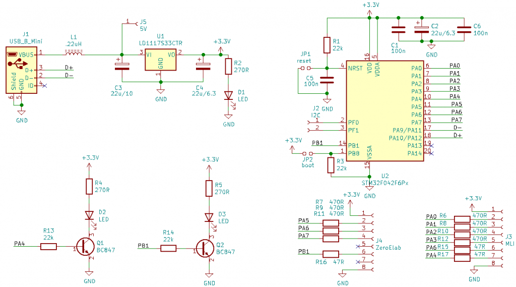
Circuit
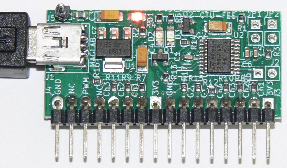
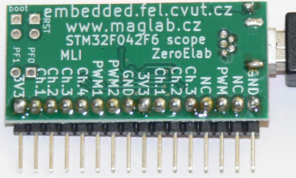
The circuit is simple, it allows to run the microcontroller, to program it through USB (using internal ST bootloader), with few serial protection resistors to save it from damage by 5V applied to non 5V-tollerant pins… few indication LEDs to show that it is powered on and outputs some signals (possibility of PWM on PA4/PB1). There are two different SW/FW packages which unfortunately use different microcontroller pins for the same functions. So there are two pin header connectors, each of them usable with appropriate software/firmware (Zeroelabviewer / MLI – Multifunctional Laboratory Instrument).
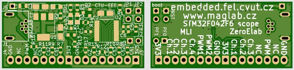
PCB
Double sided Printed Circuit Board – with through-hole USB connector for higher endurance, uses some 0603 resistors and capacitors, easy to be soldered by hand.
How to make it run?
You have to program the microcontroller first. Short the two pins marked “boot” and apply power (connect the USB). This will activate bootloader mode. Use STM32Cubeprogrammer or DFU Utils to program the bin files (STLink is not supported – SWD pins are not connected). Run the software and connect to Virtual COM port. In order to see the comport you might need to install STMicroelectronics drivers.
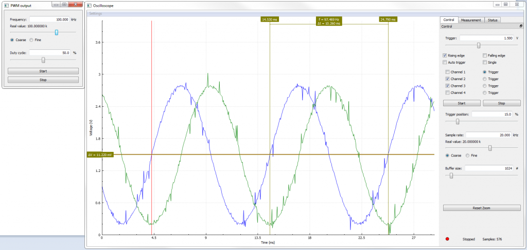
Application example
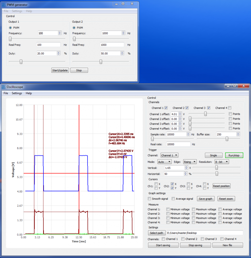
Zeroelab viewer – SDI oscilloscope used for bipolar stepper motor current monitoring (using a simple dual differential amplifier with MCP6002 op-amp…) PWM-output drives the stepper motor controller chip
MLI
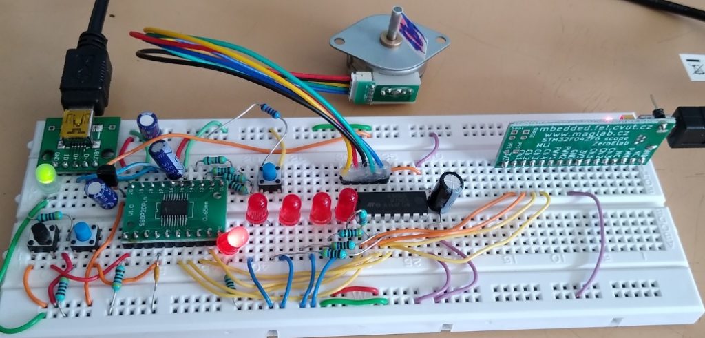
Simple optical reflective sensor – PWM generator drives a LED, another LED (or photodiode) is connected to I/V converter followed by a non-inverting amplifier (MCP6002 used). The SDI can be used to make the circuit work and to measure transfer function of the sensor (output voltage vs. distance). After evaluation of the circuit using the above mentioned SDI, the students can develop their own firmware which will be able for example to switch on some output when distance threshold is reached. The modulation is helpful for increasing the range and getting rid of the ambient light.
You can see that the software supports a lot of common features you can find on an oscilloscope – triggering, measurements, cursors…
You can download the software / firmware here: https://embedded.fel.cvut.cz/SDI
KiCAD manufacturing data download (includes circuit, PCB design, gerber files, BOM, placement file)