Created within the Team project in the first year of Master’s study program Cybernetics and Robotics at FEE, CTU in Prague – Authors: Roman Zima, Matúš Kaintz, Vít Machanec and Vojtěch Nydrle, supervised by Vojtech Petrucha (2021).
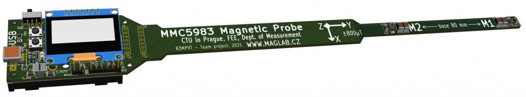
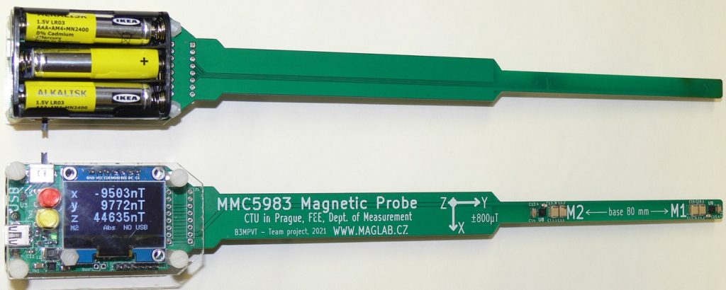
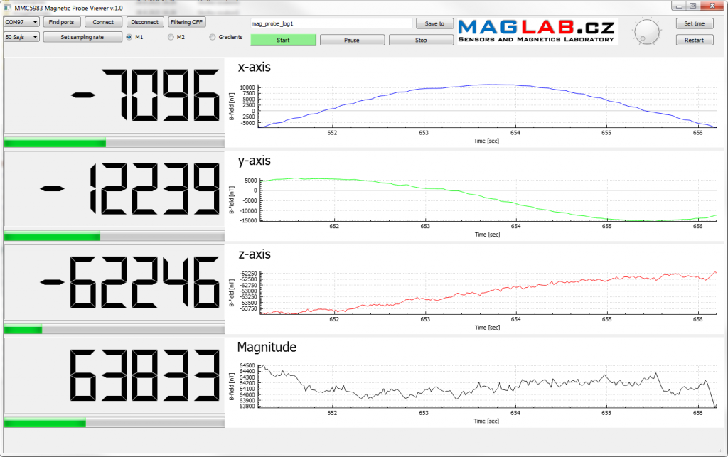
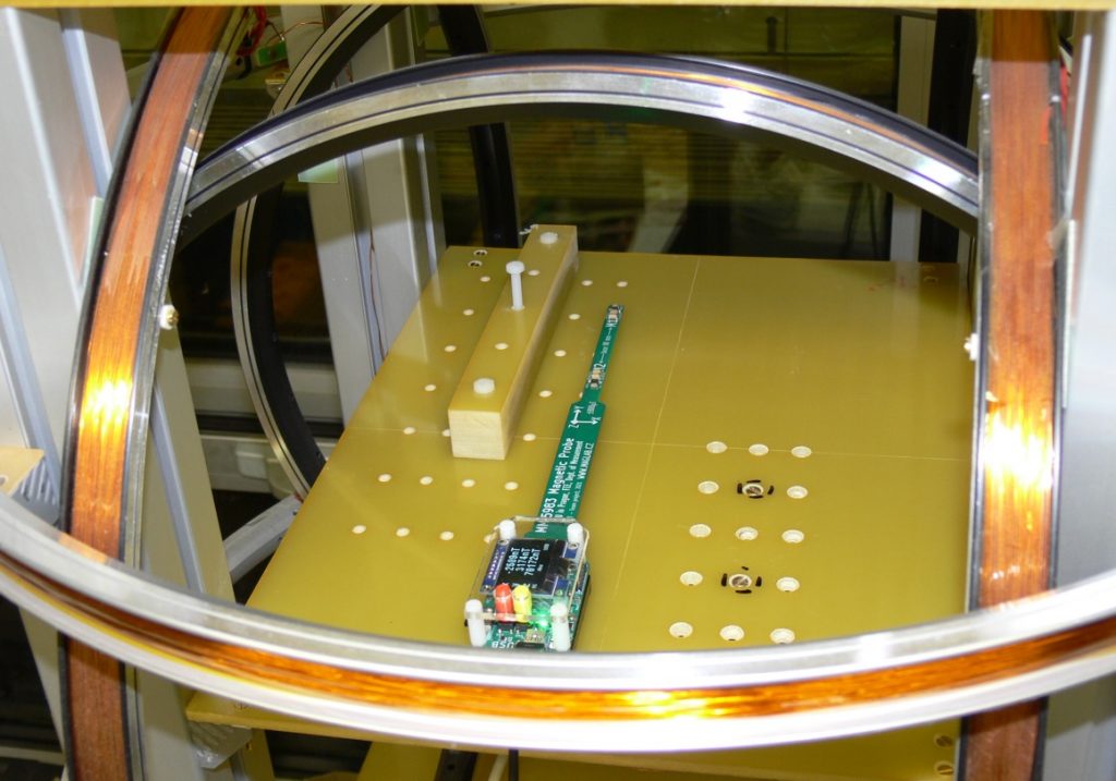
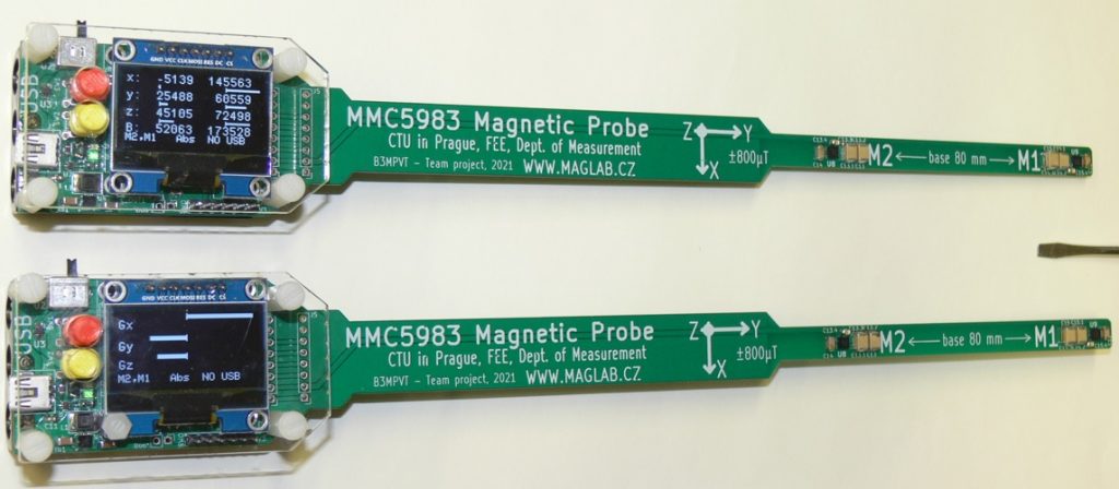
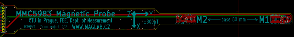
It proved to be a useful tool to roughly check the magnetic field in various places as well as the magnetic field gradient. It is based on two MEMSIC’s MMC5983 triaxial AMR sensors which allow to measure the magnetic field in the range of ±800µT with several hundred samples per second. The probe can be operated as a battery powered stand-alone tool presenting the measured values on OLED display or connected to PC through USB port. Then a specific PC application (created in Qt) can be used to visualize and store the measured values.
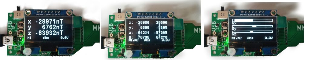
There are several modes available – switched by two pushbuttons on the probe
- Magnetic field from sensor M1 (X, Y, Z, |B|)
- Magnetic field from sensor M2 (X, Y, Z, |B|)
- Vector magnitude for M1 and M2
- Gradient between M1 and M2
- Offset calibration (zero calibration by placing the probe to magnetic field shield)
- Absolute and relative modes (subtracts current value from subsequent measurements)
- It shows digits and/or bargraphs, display can be flipped upside-down
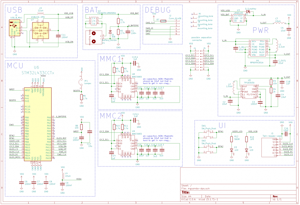
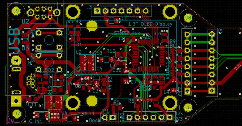
The electrical design was created in KiCAD, firmware was written with the use of STM32CubeIDE and PC application using qt framework. All source files are available below for download. All content is provided as is, absolutely without any warranty. Can be used for any purpose as long as a clear reference to this web page is provided or “Developed at CTU in Prague, FEE, Dept. of Measurements, MAGLAB.cz” reference is provided. There are still some minor problems associated with the firmware and software, in case you would create an updated/improved version, please let us know, we will post it here.
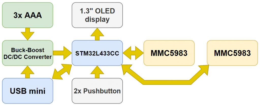
STM32L433CC is the microcontroller which runs the probe, it’s powered by 3V from buck-boost DC/DC converter supplied either from three AAA batteries or from USB. The design was created with the possibility to use two different DC/DC converter chips – RP604K301A and TPS63030 (in case one is not available). The battery is connected through LM66100 ideal diode to get maximal energy from it. 1.3” OLED display with SPI interface is used to present measured data. Magnetic sensors are connected through I2C bus, each sensor with a separate I2C, unfortunately INT signals from the sensor were not used which proved to be a bad decision. In case you do a redesign of the probe, connect them to the microcontroller… The MCU can be programmed and debugged through the SWD interface or just programmed through USB using the built-in STM bootloader activated during start-up by shorting JP1. The probe uses a specific binary data format to transfer measured values from the MCU to PC through virtual serial port – 7 bits data, log.1 at MSB indicates start of the fixed length packet, otherwise is always zero.
All the three files are zip archives, rename them to *.zip and extract them (e.g. by 7-zip)