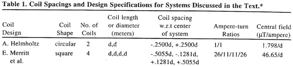

Generation of various magnetic fields is basic activity needed for magnetic sensors development testing and calibration. Ideally one can take advantage of a system that can generate an arbitrary vector of magnetic field. In this case a triaxial coil system is needed. Often the coils are made as Helm-holtz coil system (two circular coils per each axis). But there are systems available with a much higher field homogeneity suitable for more precise measurements. There are several commonly used, nicely summarized in a paper by Joseph L. Kirschvink “Uniform Magnetic Fields and Double-Wrapped Coil Systems: Improved Techniques for the Design of Bioelectromagnetic Experiments” Bioelectromagnetics 13:401-411 (1992). So-called “Merritt” design with four square coils is relatively easy to construct and generates a highly uniform field in its center.
How to make such coils?
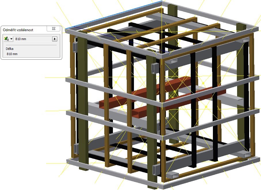
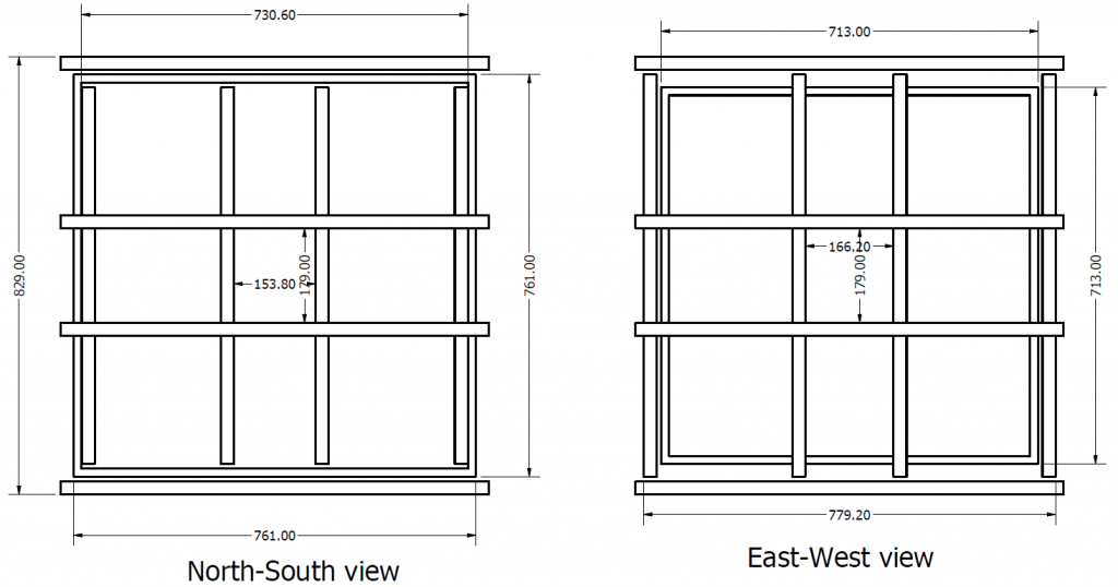
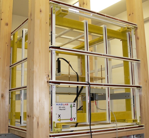
- Select final dimensions (in our case limited by available space between wooden poles used to support another coils)
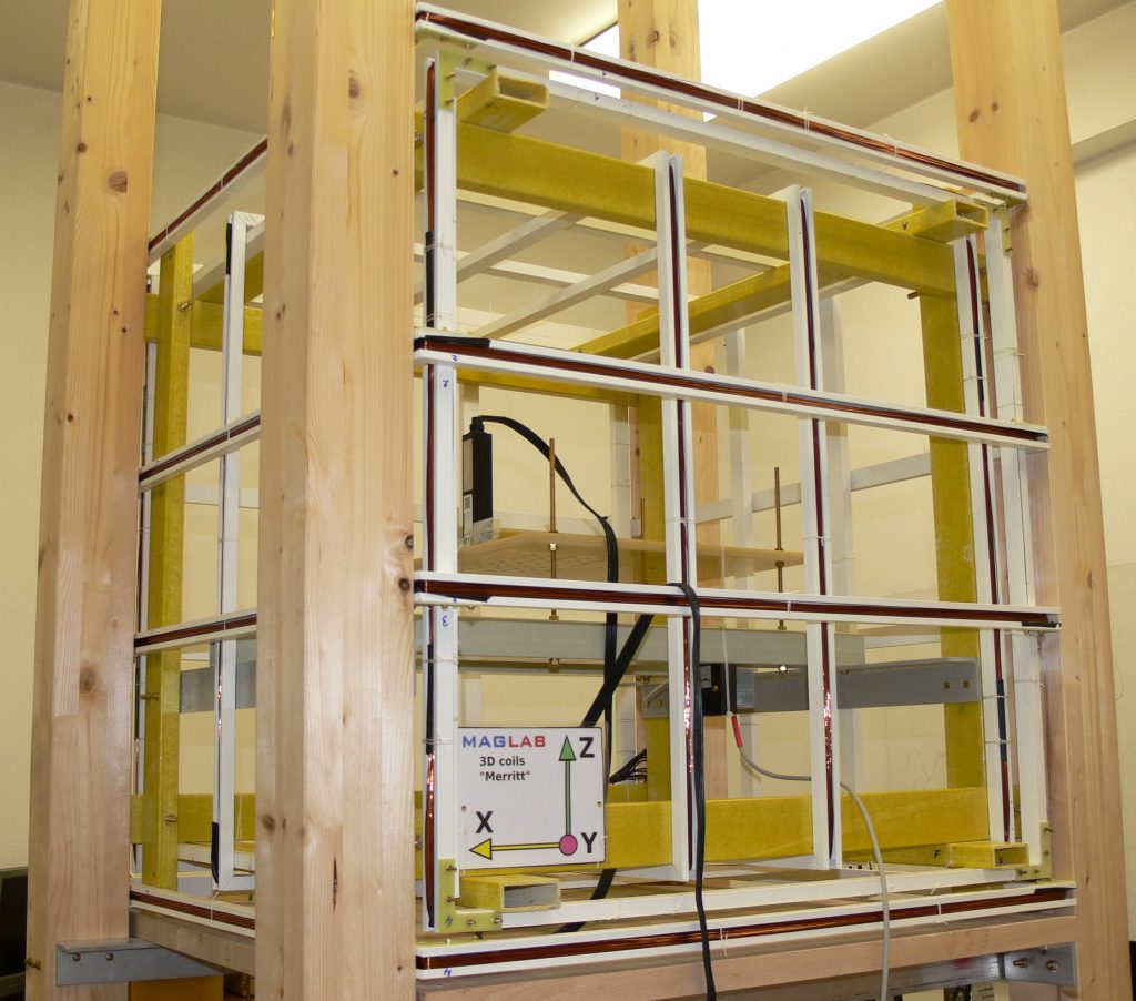
- Select coil configuration – we chose Merritt as it proved useful earlier.
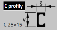
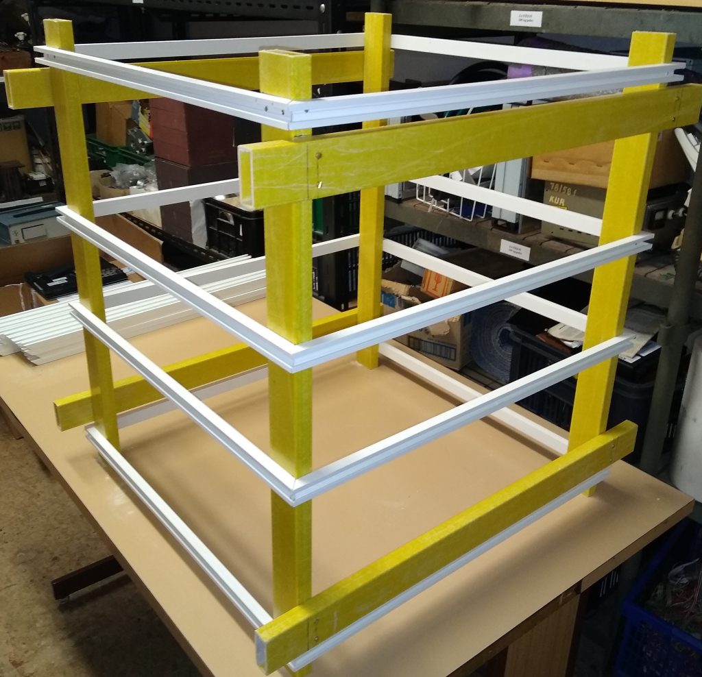
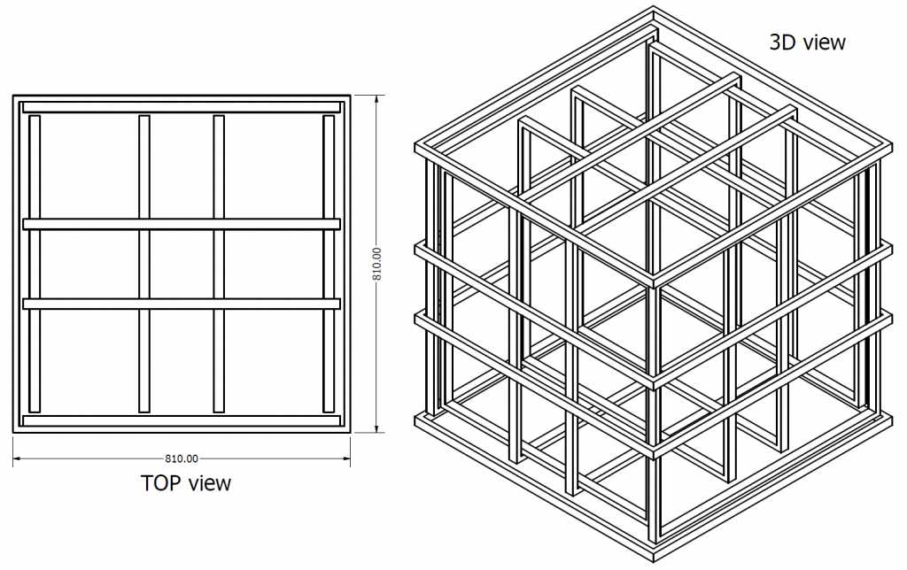
- Make a 3D model using available components to support the actual winding – in our case “C” and rectangular profiles from glass-reinforced epoxy laminate from “Prefa Kompozity” (https://www.prefa-kompozity.cz). The company can deliver the profiles precisely cut under the angle of 45 degree, so the final construction is quite easy. By clever using available profiles sizes one can minimize the number of other spacers or holders needed.
- Do not forget to estimate final coil constant (Tesla/Ampere) – often some final coil resistance value is suitable for available power sources, that determines the wire diameter and also turns count, it must be so that the winding can fit into the “C” profile, use some realistic wire filling factor. Use the coil constant and wire diameter (wire resistance) to estimate maximal magnetic field value the system can provide continuously and in pulse (we do not want to heat up the coils significantly…)
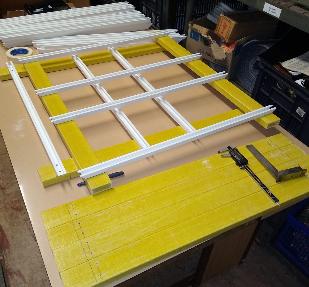
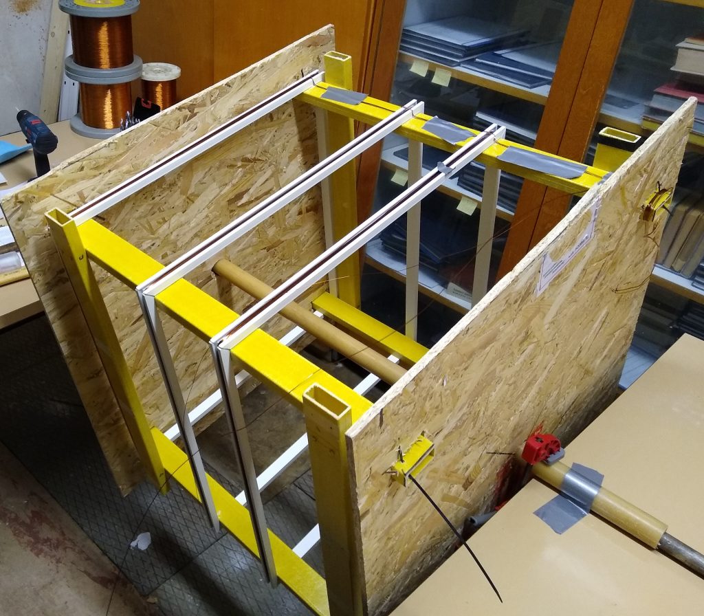
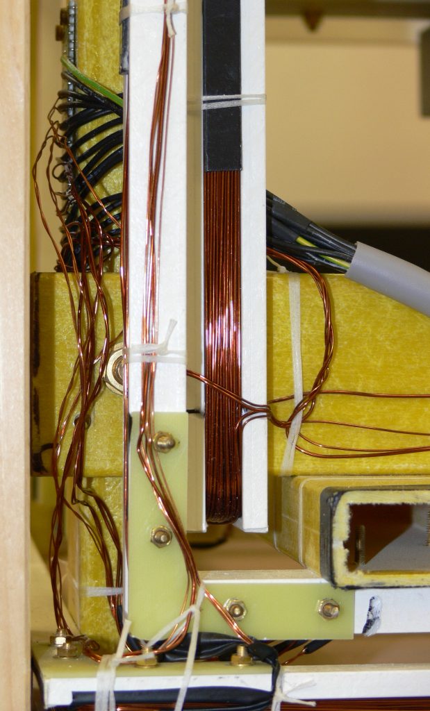
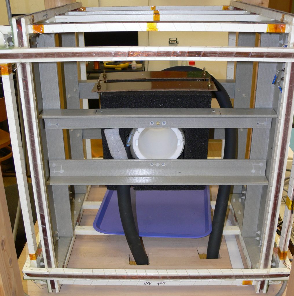
- Construct the most inner coil support and make the winding. Count the turns very carefully otherwise strong in-homogeneity can be created. This can be quite challenging, any side-thought in your brain can mean a disaster 🙂 Use only non-magnetic materials to construct the coils. Test all brass components (screws), some brass alloys can be relatively strongly magnetic, can be different from screw to screw…
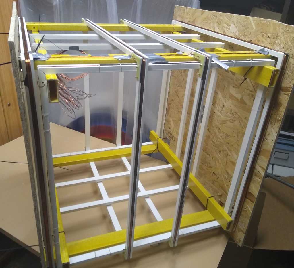
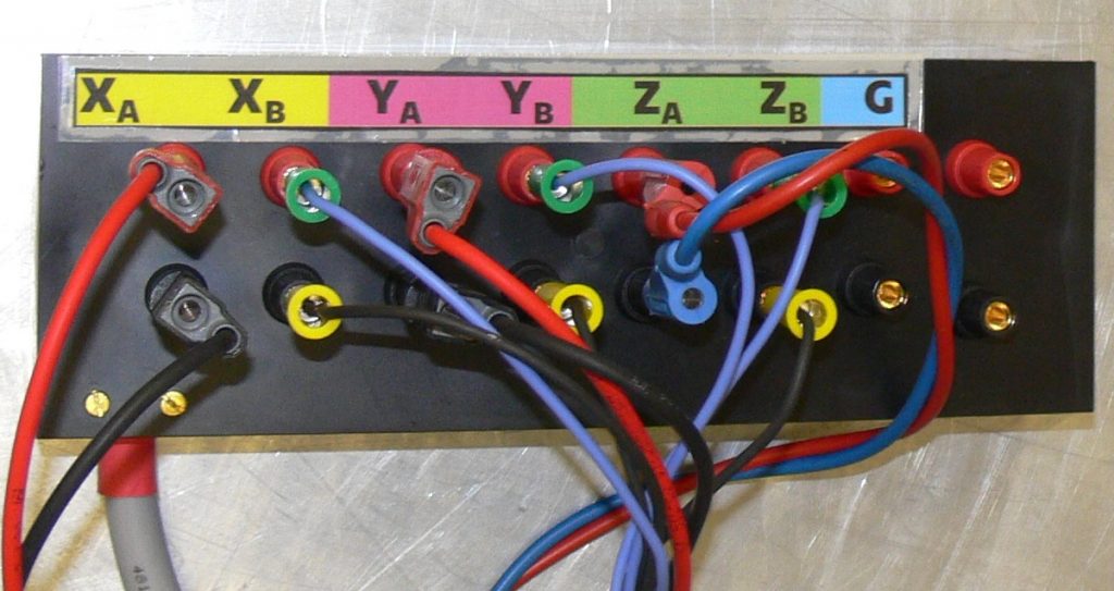
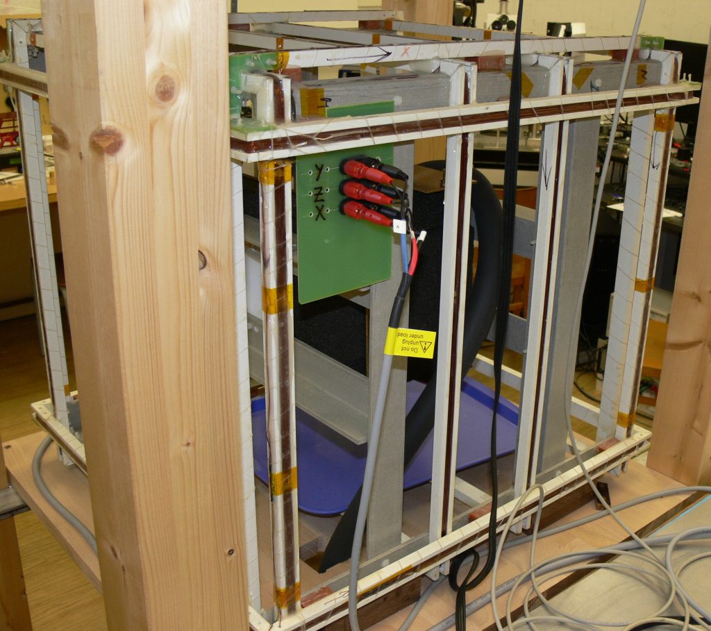
- Add two more layers to complete the full triaxial system. Measure the resistance of each coil, test each coil section by clamp ammeter (while running some current through it) to be sure that the turn counts are correct. Finally map the magnetic field inside to evaluate the result. Ask your metrological institute to calibrate the coils. If the coils are big enough (and thus the field homogeneous in a sufficient volume) you can do it by yourself for example by using precise scalar magnetometer (see e.g. Ales Zikmund et al, “Calibration procedure for triaxial magnetometers without a compensating system or moving parts” 2014 IEEE International Instrumentation and Measurement Technology Conference (I2MTC) Proceedings, or Aleš Zikmund and Pavel Ripka, “Scalar Calibration of 3-D Coil System, Journal of ELECTRICAL ENGINEERING, VOL 61. NO 7/s, 2010, 39-41)
- Add some control system (computer controllable current sources) with or without some feedback compensation (will be presented in another post).
Do you think it is too complicated? We can do such coils for you, but it is not going to be cheap 🙂